TUNNEL PHOTOMETRIC SURVEYS BY NYX HEMERA TECHNOLOGIES
Introduction
Measuring photometry in a tunnel is essential to guarantee safe, standard-compliant, energy-efficient driving conditions, and to anticipate any lighting degradation that could affect the safety and comfort of tunnel users.
With over 15 years’ experience in tunnel lighting control, the Nyx Hemera Technologies team has developed effective techniques for measuring the photometry of road tunnels accurately and efficiently, either after the installation of a new lighting system or as a preventive measure to validate the lighting at all times.
In this article, we will outline the important points to consider in the photometric measurement procedure for the tunnel lighting installation. The main objective is to determine the actual photometric distribution of the installed lighting system and to compare the results with simulated photometry and design criteria in terms of luminance, illuminance and specific ratios recommended by the IES standard for road lighting (RP-8 and LM-71, latest editions). All this to ensure safe visual conditions for motorists using the tunnel.
This document describes the procedure for measuring luminance and illuminance inside the tunnel in the various zones. The results of the studies are then presented in an official photometric measurement report.
1. Why a photometric survey?
The main purpose of a photometric survey is to determine the actual photometric distribution of the installed lighting system and to compare the results with simulated photometry and design criteria in terms of luminance, illuminance and specific ratios recommended by the IES standard for road lighting (RP-8 and LM-71, latest editions).
The results of a survey can be used to :
- Road lighting assessment: In the case of road tunnels, it is crucial to measure photometry to ensure that lighting is adequate for safety. Accurate measurement of luminance, illumination and contrast can help ensure safe driving conditions inside the tunnel.
- Checking compliance with standards: tunnels are often subject to specific lighting standards to ensure optimum safety conditions. By measuring photometry, we can check whether lighting complies with these standards, and take corrective action if necessary.
- Energy optimization: Measuring photometry in a tunnel can also be useful for optimizing lighting energy efficiency. By adjusting the lighting design according to the measurements, it is possible to reduce energy consumption while maintaining adequate lighting levels.
- Managing glare and the black hole effect: Measuring photometry in a tunnel can help assess and manage glare problems. Inadequate lighting can lead to glare conditions, which can be dangerous for road safety. The same logic applies to the black hole effect when the tunnel is under-lit.
- Preventive maintenance: By taking regular photometric measurements, lighting problems can be detected before they become critical. This enables preventive maintenance measures to be applied to ensure continuous lighting operation in the tunnel.
2. Equipment
A well-calibrated luminance meter and illuminance meter are required for photometric measurements.
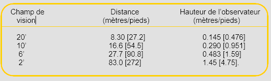
Depending on the field of view of the luminance meter used, the following distances and heights should be used.
Table 1: Measuring distances and heights
3. Tunnel features
A number of factors specific to each tunnel need to be considered before carrying out the photometric survey, in order to be able to establish an appropriate sampling grid for an effective survey that meets the needs cited in point 1 of this document.
Factors to consider are:
- The number of tubes
- Traffic management
- Number of lanes per direction
- The number of tunnel lighting zones
- GPS coordinates of the tunnel
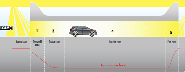
Figure 1 – Tunnel lighting zones
4. Grid placement and measurement procedure
This procedure details the grid placement and measurement procedure for one lighting zone. The procedure must be repeated for all lighting zones and lighting levels analyzed. Minimum measurement requirements must be carried out at night level, and maximum measurements at full light output. Measurements must be taken at night.
a) Confirm that the reference documents used to prepare this test plan are up to date:
- Confirm that the drawing used to position the grid point is the same as the one used during installation, to ensure that the grid point is in the first quarter of each threshold and transition zone.
- Confirm that design criteria and simulated photometric values are correct.
b) Prepare measurement grid points on the road surface
- Locate and mark the center point of each traffic lane on the line perpendicular to the identified luminaires.
- Finally, on the same perpendicular line from the previous step, add dots at 1/6 the lane width, on both sides inside the traffic lane.
This must be repeated to create the complete grid for each zone, adding additional lines spaced 2.0m to 2.5m apart. The number of lines to be added varies according to the area measured.
c) Prepare the grid measurement point on the road surface:
- The measurement point is the point from which the measurement will be taken.
d) Measuring luminance
- Position the luminance photometer at the required distance according to the field of view of the instrument used (see table in section 2) and aim at each grid point. Record the values obtained for the final report.
- Repeat for all points on the route grid.
e) Illuminance measurement
- Position the illluminance photometer on each of the grid points, use the measurement delay and move away from the device to avoid interfering with the measurement.
- Extend each row of dots along the tunnel walls and measure illuminance at 1 metre and 2 metre heights for each row of the grid.
f) Number of data recordings
- Measurements should be taken with the system in night mode and daylight mode, as well as at two other intermediate lighting levels for linear analysis in 0-10V installations for each grid point and zone.
- In the case of a contactor system, the reading must be taken at each lighting level for each point on the grid and in each zone.
g) Photos
- Photographs of the grid locations are taken with reference to the luminaires present in these environments to support the measurements that will be included in the final report.
5. Grid location for each tunnel zone
- A different grid will be created according to the characteristics of each zone, and the steps listed above will be repeated.
6. Empty data collection sheet (refers to data calculation worksheet)
- The luminance and illuminance reading data are noted and a calculation is made to produce a report containing the following data, which is compared with the photometric recommendations set out in the guidelines.
o Average maintained (cd/m2)
o Minimum average
o Maximum:minimum
o Ratio (lux:cd/m2)
o Average wall illumination (lux)
o Wall:road ratio
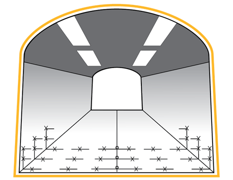
Figure 2 – Data collection sheet
Conclusion
In conclusion, photometric tunnel surveys play a crucial role in improving safe driving conditions and optimizing energy management.
Nyx Hemera Technologies, with over 15 years’ experience in tunnel lighting control, has developed precise and efficient techniques for measuring the photometry of road tunnels.
In short, these photometric surveys offer a systematic and rigorous approach to assessing tunnel lighting, ensuring optimum driving conditions in terms of safety, compliance with standards, and energy efficiency.
For more information on our photometric survey service, contact us at info@nyx-hemera.com.